Finally, time has come to put up the antenna and start having some on-air conversations. It’s nice living in the inner city and having only 7 minutes of the walking commute. Drawback is that I don’t have too much space for the antenna farm 🙁 Our house is one of those so-called ‘infills’ where the developer split the standard 50′ lot in two, so we ended up with 25′ wide piece of land. It doesn’t help being on the corner lot either, with high voltage lines running on poles parallel to the house. So, antenna tower is out of question and I decided on the hidden, attic antenna.
It’s a two storey house, narrow and long, but not long enough for 40 m dipole 😉 Its length is about 50′, running North-South, so 20 m dipole with its ~35′ fits nicely with room to spare and not to be above sleeping quarters (Safety Code 6) 🙂
I used a piece of high quality speaker cable that I got from a friend when he was working as a home theatre installer, that was scrap from one of his sites. Really nice insulated flexible wire, probably gauge 12 or maybe even 10, with finest litz wire you could find. Pain to solder, though, really thick. It was fairly easy to split and separate two wires and those ended up being the legs of the dipole.
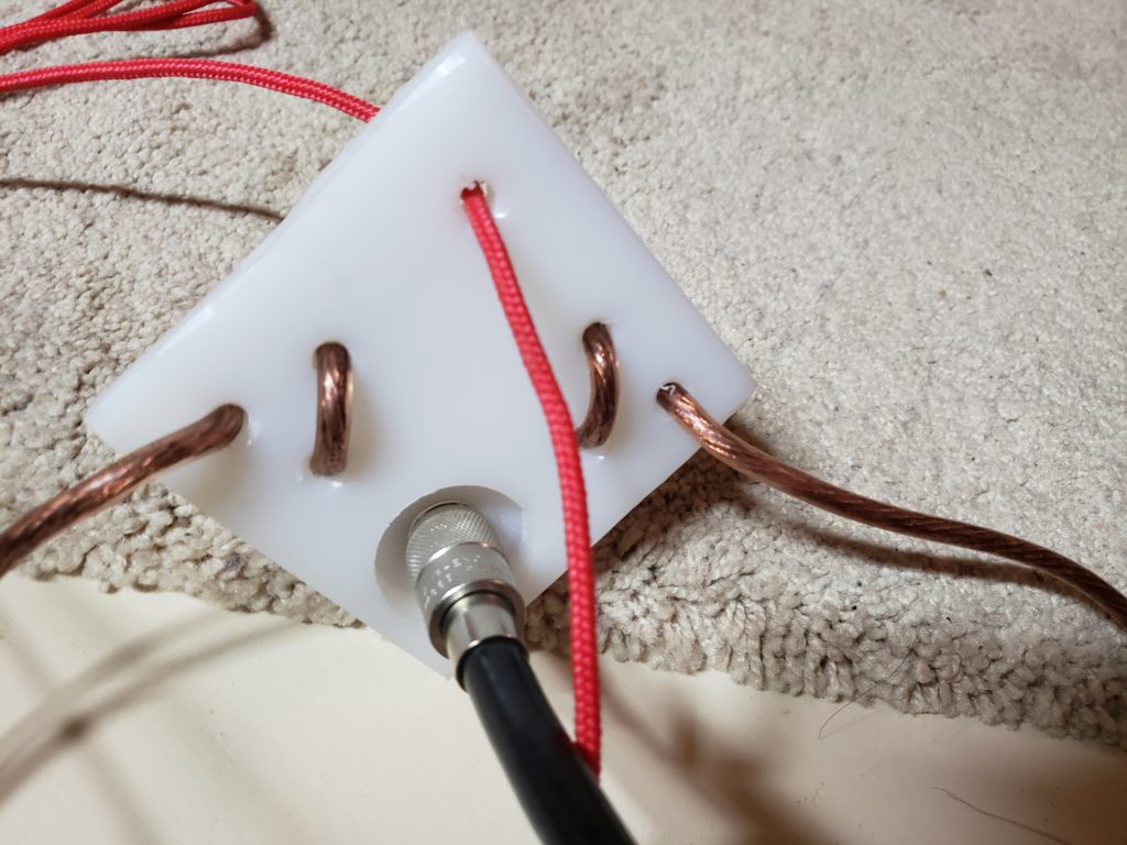
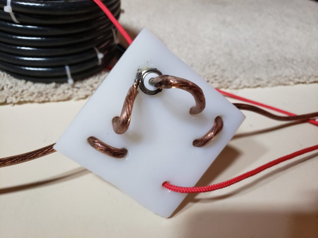
For the feed point construction, I used a piece of HDPE plastic and drilled several holes in it. The biggest one is for mounting SO-239 panel mount connector. Hole at the top is for hanging, red rope goes through it, rest of the holes where copper weaves through are for the strain relief. Legs are soldered directly to the connector on the back. Don’t judge my soldering, that connector shield really sucks the heat away. See below. But it holds.
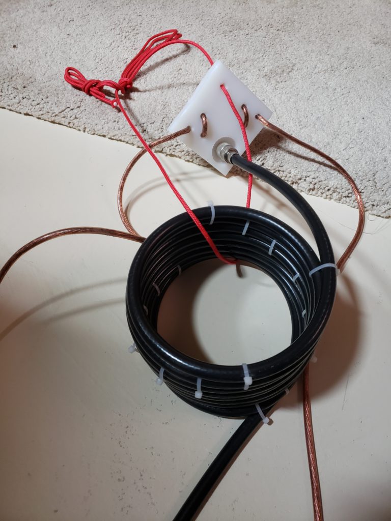
Ham radio literature says that if you are feeding the dipole directly with the coax, you may get some of the RF back to the shack on the outer side of the shield. It’s advisable to have some sort of choke to block that RF from coming back. It can be done either with some ferrite rings on the cable (cable feeds through the rings) or by basically winding the cable and creating an inductor with a shield (signal inside travels unwary, any RF on the outside encounters the inductor). Whatever variant you decide on, it should be close to the feed point. In my case, I did the latter, and wound about 8 turns of RG-8/U on approximately 6″ diameter body and fixed with some zip ties.
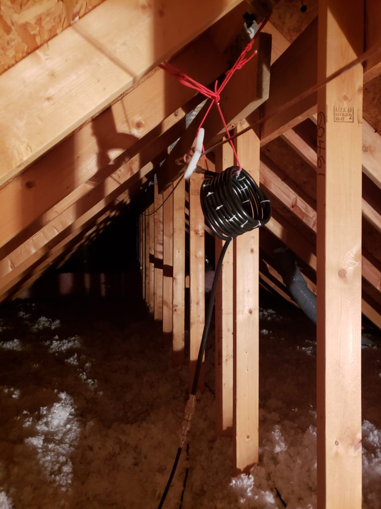
Antenna weather was really nice in the attic 😉 not windy at all, although a bit dark. I hung the feed point and ends, connected NanoVNA and started measuring. Had to climb three times to visit both ends of the dipole and gradually cut the pieces off until ended with about 1.2 of SWR on 14.100 MHz. That was good enough, since my plan is to try digital modes first. I also have an old MFJ tuner so I was able to load the antenna to 40 m and to 17 m as well. I’ll try later the other bands too, but I suspect it might work. Here’s how it looks like – keeping away from the wood and as high as possible.
Bringing the signal from/to the attic is a different story. Original plan was to establish the shack in one of the spare rooms with lots of light and sunshine, and a nice view to the outside. Since I’m not very experienced in house construction, I couldn’t find the hollow in one of the walls, so I switched to plan B. Used existing leg of coax (RG-6, 75 ohms) that was feeding one of the rooms and it goes directly to the basement where my workshop is. Already listened a bit on 20 and 17 m, heard guys from Colorado, Kentucky, Alaska, New Jersey … didn’t hear any VE/VA yet.
Now radio resides in the basement workshop, which will make grounding easier. Leaving that for tomorrow, will let you know how it goes … stay tuned!